Control a GPIO
This section will explain how to use GPIO on the IFC6410 and control it from command line. From there it is just a matter of writing the equivalent code to control the GPIO.
IMPORTANT: DragonBoard GPIO Specifics
The DragonBoard's GPIO pins use a 1.8V logic level for signaling. This means that they take in a digital signal that alternates between 0V and 1.8V.
IMPORTANT: Our Seeed sensors use either a 3.3V or 5V logic signal. This means that you need a logic level shifter to use them with the DragonBoard! Do not connect the sensors without using the proper circuitry, else you run the risk of permanently damaging the board!
Power the Sensor
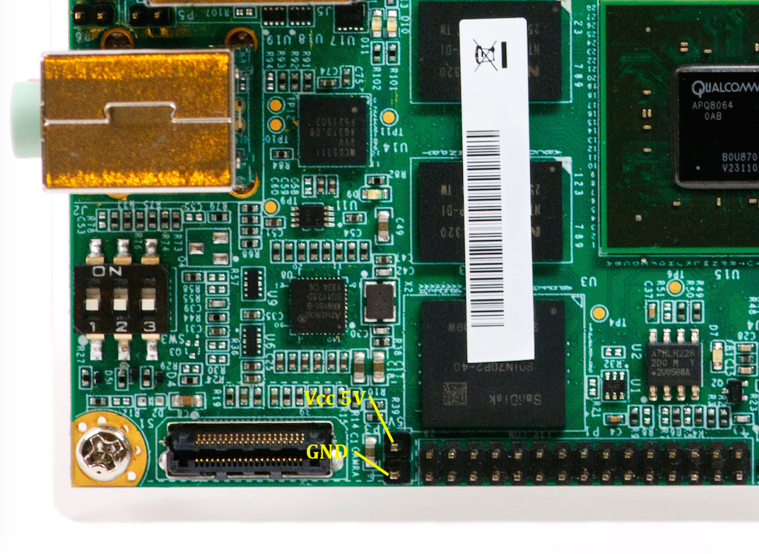
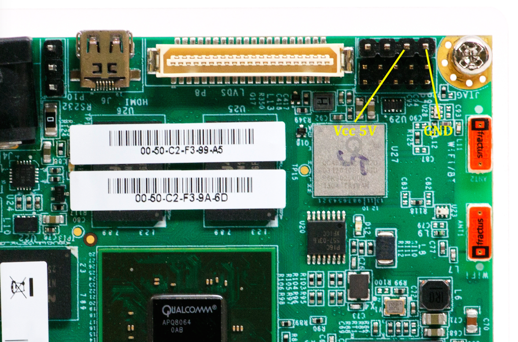
There are two header pairs on the IFC6410 that can power a 5V GPIO sensor. The images below show the locations of the pairs of Vcc-5V and Ground:
Connect the Signal
In order to signal the sensor you need to connect the correct board signal pin to the sensor's signal pin. The image below shows the 4 GPIO pins available:

Signal the GPIO
For this example we will connect to the GPIO 206 pin on the board for output and the GPIO 207 pin on the board for input. Change the 206 and 207 value to 6 or 7 to use the other pins.
First we need to set up the GPIO pin by exporting it and choosing whether it will be an input or an output pin. If you are connecting something like an LED then it should be an output pin. If you are connecting something like a Button, then it should be an input pin.
For output to the LED, this setup looks like:
$ echo 206 > /sys/class/gpio/export
$ echo out > /sys/class/gpio/gpio206/direction
For input from a Button, this setup looks like:
$ echo 207 > /sys/class/gpio/export
$ echo in > /sys/class/gpio/gpio207/direction
Now for output to an LED, we just need to write a value of 1 to the gpio file to turn it on:
$ echo 1 > /sys/class/gpio/gpio206/value
And to turn it off you would write a 0 to the file:
$ echo 0 > /sys/class/gpio/gpio206/value
Similarly from command line if you wanted to check the status of the input GPIO, you would display the contents of the input pin file:
$ cat /sys/class/gpio/gpio207/value
Now you just need to mimic this in software to control the GIPO pins.